
Building Information Modeling (BIM) has established itself as a linchpin of the Architecture, Engineering, and Construction (AEC) industry. Its increasing prominence is a result of its unparalleled capacity to consolidate and streamline all project data, increase collaboration across stakeholders, and drive better outcomes for projects overall.
Tied very closely to BIM is the idea of Level of Detail (LOD). LOD makes it easier to deal with complicated 3D models. It ensures that the appropriate level of detail is provided for every project phase.
In this article, we will provide valuable guidance on how to use LOD in practice. We will look at each of the LOD levels and give recommendations on how to best use them in your projects. Having a clear understanding of LOD is essential to fully realizing the power of BIM and keeping your projects on-track and under budget. Moreover, it ensures you don’t receive excessive information delivery, much of which may not be needed and could be costing you money.
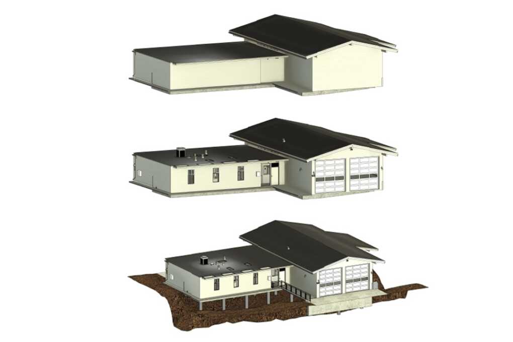
Photo https://alterpex.com/cad-to-bim-conversion-services
What is Level of Development (LOD)?
Level of Development (LOD) specifies the degree of completeness and precision contained within a Building Information Model (BIM). Most importantly, it’s one of the best ways to establish consistency with how project teams communicate information about the reliability of the information contained in the model.
Consider it the BIM industry’s lingua franca. Everyone who touches the project has it available to them to quickly identify what’s reliable and what’s not.
The LOD framework operates on a scale of 100 to 500. Each digit signifies a varying level of detail as the project moves forward.
The necessity of understanding LOD is crucial when planning, developing, and delivering a project.
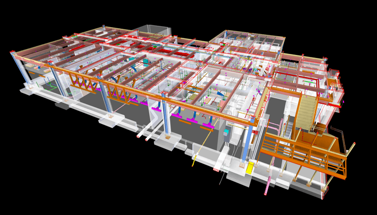
Photo https://alterpex.com/bim-architectural-services
Overview of LOD Levels
LOD 100 – Conceptual
This is the starting design level, with an emphasis on the concept and overall shape. The model only contains abstract representations of the elements. No real geometry or spatial relationships are defined. This level is often employed in feasibility studies, site massing, or other early-stage planning scenarios. It’s helpful for upstream policy and planning level decision-making like zoning, big ticket project budgeting, and high-level site analysis.
LOD 200 – Approximate Geometry
LOD 200 defines generic systems or assemblies with approximate shape, size, and topological orientation. It is still very schematic but begins to depict real-world proportions and relationships.
At LOD 200, elements are shown as models with generic placeholders. Model elements are modeled as approximate systems or assemblies. For example, an HVAC unit with a generic configuration or a generic door.
It may include dimensions, quantities, locations, and orientations stated as a general range or in generalized terms. This works well for early design development, multi-discipline coordination, and early-stage quantity takeoffs. It aids in creating spatial planning and early cost approximation.
LOD 300 – Precise Geometry
LOD 300 involves accurate modeling or design suitable for coordination. Geometry and modeling include accurate dimensions, forms, and positioning of elements. The model can now be used for construction documentation, clash detection, and multidisciplinary coordination.
LOD 350 – Detailed Coordination
At LOD 350, model elements are developed with precise geometry and clearly defined relationships to other building components. This level introduces a key layer of information: how systems connect, interact, and are supported in the built environment.
Every modeled element — ducts, pipes, conduits, structural members, equipment — is shown with the necessary supports, connections, and penetrations. That includes brackets, hangers, embeds, openings in walls or slabs, and other interface elements. The goal is to represent not just the element itself but its physical integration with the surrounding systems.
LOD 350 allows teams to identify and resolve coordination issues before construction.
LOD 400 – Fabrication
LOD 400 pushes the model into the build phase. This is where design turns into production. Every component at this level includes the exact geometry, dimensions, connections, and specs needed for fabrication or on-site assembly.
For example, a steel beam won’t just show size and location. It’ll include the shop-specific cut lengths, plate details, connection types, and the layout of bolts. Ductwork will show seam locations, fitting types, and hanger spacing.
Keep in mind, LOD 400 isn’t required for every element. It’s used where it adds value, usually for systems that are prefabricated.
LOD 500 – As-built Models
LOD 500 represents verified, field-accurate information. At this level, all model elements are confirmed through field verification. This can include manual measurement, laser scanning, or updated redlines. Dimensions, locations, materials, and attributes are recorded based on what was installed, not what was originally specified.
Each component should include data useful for facility management. That typically means manufacturer details, model numbers, serial numbers, installation dates, and maintenance schedules. LOD 500 models are used for long-term operations and asset management, not construction.
Understanding LOD standards is essential for using BIM effectively across project phases. Each level, from 100 to 500, serves a specific purpose. Misapplying these levels leads to confusion, rework, and unnecessary costs.
Teams must define LOD expectations clearly in the BIM Execution Plan. Alignment across trades is critical. Without that, even a technically correct model won’t deliver value.
Use LOD strategically. Not every element needs to reach LOD 400 or 500. Model what’s necessary, based on scope, risk, and project goals.
In short, LOD standards give structure to modeling. Applied properly, they improve collaboration, reduce field issues, and support the full building lifecycle.